- Home
- Major projects
- Processes
WATER TREATMENT
- CHLORINATION
- ELECTRODEIONIZATION (EDI)
- ULTRAVIOLET (UV) DISINFECTION FOR WATER TREATMENT
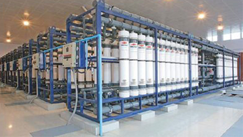
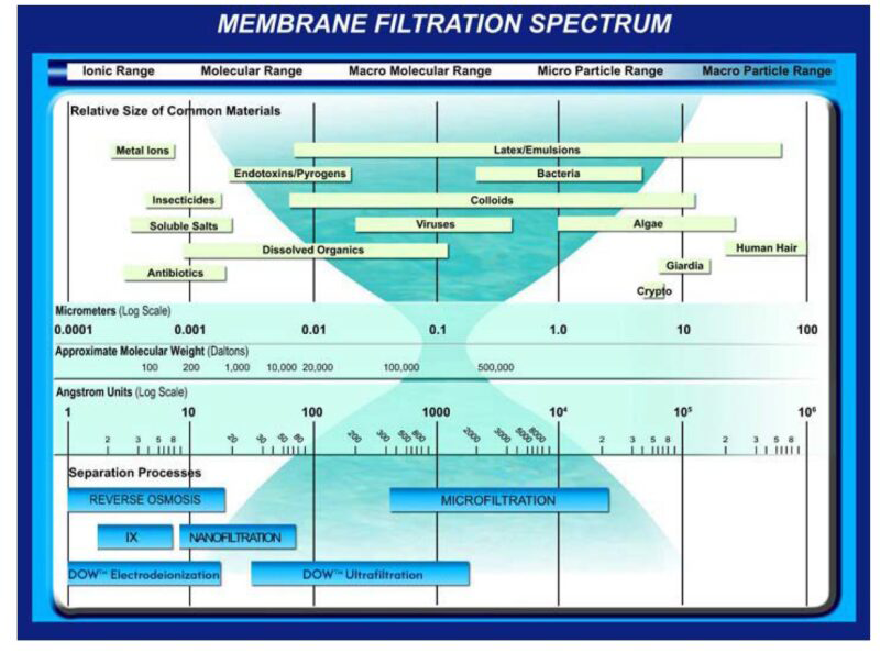
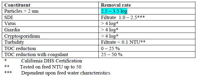
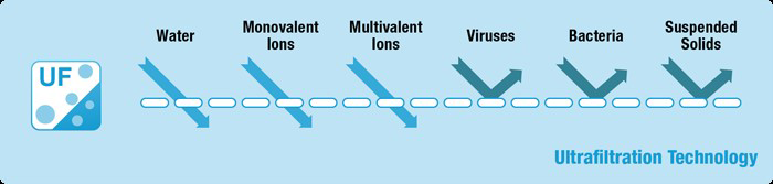
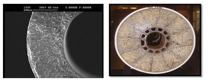
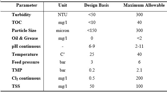
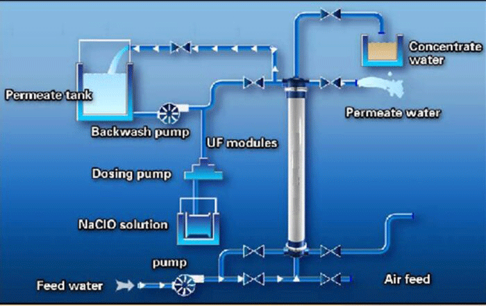
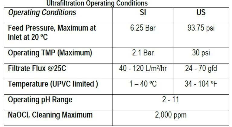
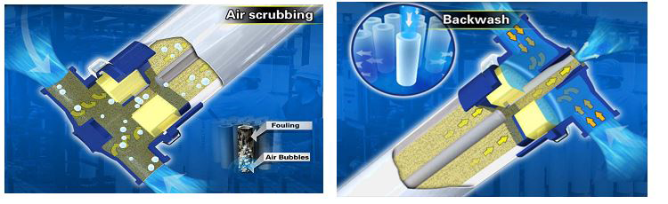
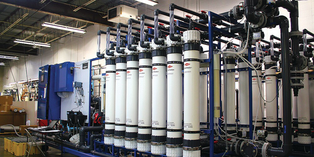
- ULTRAFILTRATION (UF)
- SLOW SAND AND DIATOMACEOUS EARTH FILTRATION
- REVERSE OSMOSIS (RO)
- MICROFILTRATION (MF)
- RAPID GRANULAR BED FILTRATION
- Nanofiltration (NF)
- OZONE DISINFECTION
- PRESSURE SAND FILTERS
- MIXED BED ION EXCHANGE (IX)
- GRANULAR ACTIVATED CARBON FILTER
- ION EXCHANGE RESIN WATER SOFTENER
- MEDIA FILTRATION
WATER TREATMENT
- Moving Bed Biofilm Reactor (MBBR)
- Upflow Sludge Blanket Filtration (USBF)
- Sequencing batch reactor (SBR)
- Rotating Biological Contactor (RBC)
- DISSOLVED AIR FLOTATION (DAF)
- Conventional Activated Sludge (CAS)
- API (American Petroleum Institute)
- Membrane bioreactor (MBR)
- Intermittently Decanted Extended Aeration (IDEA)
- CPI (Corrugated Plate Interceptors)
- Integrated Fixed Film Activated Sludge (IFAS)
- Extended Aeration Activated Sludge (EAAS)
- Equipment supply
- About us
- Contact us